Binder and Inclusions Example
XML Input File
The basename for this file is pbx_2D.xml.
The file can be run using this command:
microstructpy --demo=pbx_2D.xml
The full text of the file is:
<?xml version="1.0" encoding="UTF-8"?>
<input>
    <material>
        <name> Binder </name>
        <material_type> matrix </material_type>
        <fraction> 35 </fraction>
        <shape> circle </shape>
        <size>
            <dist_type> uniform </dist_type>
            <loc> 0.08 </loc>
            <scale> 0.08 </scale>
        </size>
        <color> lightgray </color>
    </material>

    <material>
        <name> Inclusions </name>
        <material_type> crystalline </material_type>
        <fraction> 65 </fraction>
        <shape> circle </shape>
        <size>
            <dist_type> lognorm </dist_type>
            <scale> 0.35 </scale>
            <s> 0.35 </s>
        </size>
        <color> darkorange </color>
    </material>

    <domain>
        <shape> square </shape>
        <side_length> 3 </side_length>
        <corner> (0, 0) </corner>
        <periodic> True </periodic>
    </domain>

    <settings>
        <directory> pbx_2D </directory>
        <verbose> True </verbose>
        <rng_seeds>
            <size> 1 </size>
            <position> 1 </position>
        </rng_seeds>

        <!-- the overlap tolerance: with 0.5 all the seeds can be placed -->
        <rtol> 0.5 </rtol>

        <!-- the seeds and the grains stay a margin away from the periodic
             faces, or cross them by more than the margin: auto is half the
             target edge length, at most an eighth of the smallest grain -->
        <periodic_margin> auto </periodic_margin>
        <edge_opt> True </edge_opt>
        <edge_opt_n_iter> 25 </edge_opt_n_iter>

        <mesh_min_angle> 25 </mesh_min_angle>
        <mesh_max_volume> 0.01 </mesh_max_volume>

        <seeds_kwargs>
            <linewidth> 0.3 </linewidth>
        </seeds_kwargs>
        <poly_kwargs>
            <linewidth> 0.3 </linewidth>
        </poly_kwargs>
        <tri_kwargs>
            <linewidth> 0.15 </linewidth>
        </tri_kwargs>
    </settings>
</input>
Materials
This microstructure is a particulate composite, such as a plastic-bonded explosive: crystalline inclusions in a polymer binder.
The first material is the binder, a matrix phase that makes up 35% of the
area.
Its seeds are small circles: the cells of a matrix phase are merged into one
region, so the seeds only need to fill the space between the inclusions.
The second material is the inclusions, a crystalline phase that makes up
65% of the area, with circular seeds whose diameters follow a lognormal
distribution.
Each seed of a crystalline phase becomes one polygonal grain of the mesh.
Domain Geometry
The materials fill a square domain of side length 3, periodic in both directions.
Settings
The overlap tolerance rtol is set to 0.5: with the default fitted value
some of the small binder seeds do not fit between the inclusions and are
rejected.
The random number generator seeds make the microstructure repeatable.
The seeds are placed a margin away from the periodic faces (periodic_margin
set to auto: half the target edge length, or an eighth of the smallest
grain if that is smaller) and the edge optimization moves the seeds that
leave a thin piece of a grain on a face, a corner narrower than the minimum
angle of the mesh, or a very short edge, since any of these forces very
small triangles.
The mesh has a minimum angle of 25 degrees and a maximum element area of 0.01.
Output Files
The three plots that this file generates are the seeding, the polygon mesh, and the triangular mesh. These three plots are shown in Fig. 26 - Fig. 28. The binder is one region of the mesh. Its boundaries with the inclusions are facets of the mesh.
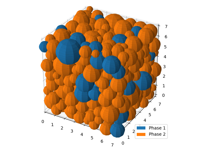
Fig. 26 Binder and inclusions example - seed geometries.
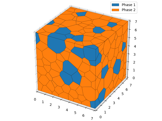
Fig. 27 Binder and inclusions example - polygonal mesh.
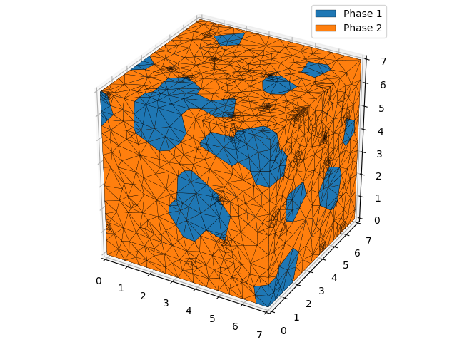
Fig. 28 Binder and inclusions example - triangular mesh.
